Ayuda de DP21
Recuperamos el fichero de ayuda en otro formato, y lo presentamos en formato de RED (.htm):
Los Comandos y Menu, en Help of DP21_MENU
The Contents lists Help topics available for Puertra, Version 21 for Windows 95 and Windows98 (WPU21). Use the scroll bar to see entries not currently visible in the Help window. To learn how to use Help, press F1 or choose Using Help from the Help menu. Main Topics

Rige
Getting Started
Formal Rules
Menu
Commands
Rige Edition
Rige Finishing
References
Using Puertra is easy: just by running it, a Rige is loaded (INI.RIG) and a TE appears. You can move it across the surface, change its size and go through all Menu items, seeing the result on the display, and so learning the use and meaning of the Commands. The Formal Rules are a set of descriptive properties of Rige that summarize a Tradition, a way of designing Rige as well as its Aesthetics.
The modification of an existing Form, that is the Lattice and Rige, is somewhat more difficult since you must first have understood the meanings and relationships between Angles and Distances, as well as the Symmetries applied to the Generative Element and the Translation Element.
The last and final step is the design of new Riges inside new Lattices, with or without Metabolai; you need some knowledge of elementary geometry and, above all, good taste and artistic feeling: Art is based on a sensible choice among thousands of possibilities, and only the mentioned qualities can guide you to reach beautiful forms, as the former inventors of Rige did, with infinitely less material resources (such as Puertra!) than us, but probably with infinitely more coherent and meaningful ways of living.
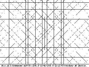
PUERTRA is a
package developed by Aldebaran Soft, that generates, draws, edits and
colours the Islamic Geometric Interlaced Lattices, Rige, which we label
Doors of Tradition, because these Rige are often found on mosque doors
and windows. These forms express, in numeric symbolism, relationships with
the Abstract and the Absolute.
The nucleus of PUERTRA is a theoretical model of the Rige, consisting on two main parts:
1. The Lattice, consisting of a series of parallel straight lines, regularly spaced, and intersecting each other in nodes, forming segments between every two nodes.
2. The Generative Element (GE): is a selection of some of these segments in order to form a pattern inside a triangle. By rotating this triangle round a centre, a form with circular symmetry is created, the TE (Translation Element), which, repeated by translation in two dimensions, covers the plane.
The design is made in five stages:
1. Didactic Sketch of GE.
2. Circular Repetition of GE, becoming the TE.
3. Plane covering by translation, with colours and interlacing.
4. Colored background.
5. Framing of the form with a variety of patterns fitting in with lattice properties.
COMPUTER IMPLEMENTATIONThe forms and designs described above can be determined and actually drawn by the program PUERTRA, in an easy and didactic way. PUERTRA, acronym of PUERTAS de la TRADICION (DOORS of TRADITION), allows the user to choose order, distances, angles, segments, interlacing, frames, colours, and any other formal aspect of a Rige. This Help facility lists the main commands of PUERTRA. Several Submenus inform on other possibilities as well.
With this assistance, beautiful and didactic forms can be designed, and printed with any of the available programs to capture, display, graphics-format convert, edit and print in black/white or color. All the figures that appear in this Help have been designed with PUERTRA, unless said otherwise.
During the program running, sizes, proportions, colours and textures, for both background and frames, can be changed on a trial and error basis. A more careful edition can also be chosen, where the main parameters of the form can be changed to modify or create a new one. Any Rige can be stored on disk for later recovering with all its original parameters; with this facility, a big library can be created ‒each Rige occupies only 1-4 Kbytes.
Aldebaran Software. 1999
 The lattice
is a family of families of straight lines. Several straight lines compose
each family, all parallel among themselves. The Distances
between each pair of neighbouring straight lines take only a few different
values, usually two. These values are linked to the lattice Order
as well as the Angles
between families. In simple cases, there is only one sublattice in a
Lattice, and, the same series of distances for all the Angles. But in
complex forms, it is possible to find 2 or 3 Sublattices; in each one,
several Subseries of distances according to its different angle, and in each
one of this subseries, different number and values of these distances. See
Lattice Edition.
The lattice
is a family of families of straight lines. Several straight lines compose
each family, all parallel among themselves. The Distances
between each pair of neighbouring straight lines take only a few different
values, usually two. These values are linked to the lattice Order
as well as the Angles
between families. In simple cases, there is only one sublattice in a
Lattice, and, the same series of distances for all the Angles. But in
complex forms, it is possible to find 2 or 3 Sublattices; in each one,
several Subseries of distances according to its different angle, and in each
one of this subseries, different number and values of these distances. See
Lattice Edition.
The order of a lattice, N, is a natural integer. This number is the number of different directions present in the lattice, or, equivalently, the number of Angles. The angle between any two directions is a multiple of a single angle, the Basic Angle, which means that these directions are parallel to the radius of a circumference divided in N parts. The order is usually even. The most usual values are 6, 8, 10 and 12. Others also found are 20, 24, 32, 36. But 14, 28, and big numbers are extremely rare. In theory, the order of a lattice could be any integer, but constructive, psychological, aesthetic and mathematical reasons limit its values to small numbers with many divisors. Typical cases are 8, 10, 16, 20, 24 and 32. The constructive reasons are (or were) the difficulty of making wood, plaster, ceramic pieces with extremely fine angles, and with too many possibilities: in a 36-lattice there may appear angles of 10, 20, 30, ... 350 degrees, 35 different values. The tools would have to have been very exact, which was not easy in medieval times. The psychological reasons relay on the difficulty in perceiving so many different angles and distances. This leads us to aesthetics: the sense of unity is lost as in an intricate and baroque relief. Some mathematical reasons can also be found, probably related to the former: the higher the order, the more polygons are possible and the lattice will need many different distances, complicating again the form for designer, maker and observer. Continue studying the Distances in relation to the Angles for a specific Order. As we said in Order and in Lattice , all the angles that appear in a Rige are multiples of a basic one, which value is the Nth part of the full circle, that is, 360º/N, being N the Order of the Lattice. All the segments in the Rige are parallel to one of these angles, except when the Rige includes more then one Lattice, thus becoming what we have called Metabolê ‒plural: Metabolai. Continue studying the Distances in relation to the Angles for a specific Order. Let us expand further this subject of distances between the straight lines of a family. If we do not impose any symmetrical rule, any distance is possible. But if we do, as Tradition demands, once we choose one, the gyration for central symmetry will create 'alias' in another radius, thus creating new distances as a necessity. Let us see some cases from the simplest to some more complicated ones.
ORDER 6. This is a very simple case. The angles are the 6 multiples of alfa=360°/6=60° that is, 0º, 60º, 120º, 180º, 240º and 300º. If we consider a triangle, it must be equilateral and the angles will be 60º, 60º, 60º. If we choose any distance on the horizontal as a side, the same distance appears by rotating it on the oblique side, for equilateral. Thus we have only one distance necessary in the case N=6. We can use more, of course, but the order does not impose it, one is enough. See Fig.1.
ORDER 8. It is a simple, but already interesting case. The angles are the 7 multiples of alpha = 360°/8=45°, that is, 45º, 90º, 135º, 180º, 225º, 270º and 315º. If we consider a triangle with angles 45º-45º-90º, once we gyrate the hypotenuse on the horizontal side, we obtain a new distance as a consequence of the first one. The ratio between them is V2/1 =V2 (V means 'squ are root
of'). So
are root
of'). So the lattice order implies a specific distance ratio. See this ratio
in Fig.2. Now the problem is to know how many different distances we need.
If we raise another perpendicular to the horizontal at point V2, the new
distance on the diagonal will be V2 x V2 = 2. But this distance is 2
times 1, that is, a distance equal to the first, 1: we do not need another
distance in this case. In general, any gyration of a linear combination of
these two distances, 1 and V2, will provide us with another combination of
them: they form what is known as a Vector Space, with 1 and V2 as a Base of
the Space: (a+bV2) x V2 = 2b + aV2 = b' + aV2.
ORDER 10.
A very interesting and very beautiful case. The angles are the 10 multiples
of alfa=360°/10=36°, that is, 0, 36, 72, 108, 144, 180º, and their
axial symmetries with the horizontal. A simple triangle will be the
isosceles 36º-72º-72º. Once the base of the triangle is chosen, the
distances between parallels that appear now in the triangle are its heights.
The ratio of their values is found to be, after a little counting,
1.6180.... But this is a prestigious number, older than the civilizations
about which we are talking: this is the "Golden Proportion", considered as a
very harmonic ratio of two distances (like a picture frame, for instance).
Its exact value is (1+V5)/2; let us call it PHI. If now, we
take another triangle with the smaller height equal to a linear combination
of 1 and PHI, with coefficients a, b, the other one will be: (a+b PHI) x
PHI = a PHI + b PHI x PHI. But PHI x PHI = (1+V5)/2 x
(1+V5)/2 = (1+5+2V5)/4 = (3+V5)/2 =1+PHI therefore (a+ b PHI) x
PHI = a PHI + b (PHI x PHI) = a PHI + b (1+PHI) = b + (a+b) PHI = b + a'
PHI what means that also the other height is a linear combination of
1 and PHI, and, again in this 10-space, the pair (1, PHI) is a base vector.
For instance, in Fig.3, all the distances are equal to 1, PHI, 1-PHI or any
other linear combination. Beautiful and well-known relations can be found
for this number PHI; see several developments of this subject in
[Coxeter,1973. Ghica, 1977. Rademacher & Toeplitz,1970].
the lattice order implies a specific distance ratio. See this ratio
in Fig.2. Now the problem is to know how many different distances we need.
If we raise another perpendicular to the horizontal at point V2, the new
distance on the diagonal will be V2 x V2 = 2. But this distance is 2
times 1, that is, a distance equal to the first, 1: we do not need another
distance in this case. In general, any gyration of a linear combination of
these two distances, 1 and V2, will provide us with another combination of
them: they form what is known as a Vector Space, with 1 and V2 as a Base of
the Space: (a+bV2) x V2 = 2b + aV2 = b' + aV2.
ORDER 10.
A very interesting and very beautiful case. The angles are the 10 multiples
of alfa=360°/10=36°, that is, 0, 36, 72, 108, 144, 180º, and their
axial symmetries with the horizontal. A simple triangle will be the
isosceles 36º-72º-72º. Once the base of the triangle is chosen, the
distances between parallels that appear now in the triangle are its heights.
The ratio of their values is found to be, after a little counting,
1.6180.... But this is a prestigious number, older than the civilizations
about which we are talking: this is the "Golden Proportion", considered as a
very harmonic ratio of two distances (like a picture frame, for instance).
Its exact value is (1+V5)/2; let us call it PHI. If now, we
take another triangle with the smaller height equal to a linear combination
of 1 and PHI, with coefficients a, b, the other one will be: (a+b PHI) x
PHI = a PHI + b PHI x PHI. But PHI x PHI = (1+V5)/2 x
(1+V5)/2 = (1+5+2V5)/4 = (3+V5)/2 =1+PHI therefore (a+ b PHI) x
PHI = a PHI + b (PHI x PHI) = a PHI + b (1+PHI) = b + (a+b) PHI = b + a'
PHI what means that also the other height is a linear combination of
1 and PHI, and, again in this 10-space, the pair (1, PHI) is a base vector.
For instance, in Fig.3, all the distances are equal to 1, PHI, 1-PHI or any
other linear combination. Beautiful and well-known relations can be found
for this number PHI; see several developments of this subject in
[Coxeter,1973. Ghica, 1977. Rademacher & Toeplitz,1970].GENERAL CASE. As we have seen in the former cases, any order which engenders in other radii distances which can be expressed as a linear combination of two, will accept this pair as a base, and any linear combination of them, or what is equal, the distance between any two straight lines of the same series, will form a legal or permitted triangle (with vertices on some nodes of the lattice), by using some other combinations of the base vectors.
Since any elemental figure (EE) of a Rige can be decomposed into triangles, the found basis also allows legal Rige, and therefore constitutes answers (not all, but some) to the question raised about the distances between straight series. In Table 1 we can see some of these answers. In it are also shown several possible polygons in each lattice, some of which were shown in the contiguous figures. In Table 1 are listed base vector ratios for greater values of N, obtained by the former expression, which are also equal to the value 2 cos(p/n), deduced by simple geometric calculus. TABLE 1. N-LATTICE RATIO|
N |
a/b=2cos(p/n) |
a/b exact |
| 6 | 1 | 1 |
| 8 | 1.4142.... | V2 / 2 |
| 10 | 1.6180 ... | (V5+1)/2 |
| 12 | 1.7320... | V3 |
| 14 | 1.8019... | |
| 16 | 1.8477... | |
| 18 | 1.8793... | |
| 20 | 1.9021 | |
|
22 |
1.9189... |
|
Symmetries are an essential characteristic of Rige artistic design. They create internal similarities within the form itself, which so acquire a psychological pregnancy, that is, attract the eye interest and becomes centers of attention, able to convey meanings, to become symbols. From the geometric point of view, three types of symmetries appear in Rige figures:
1. Circular: with a point that acts as a center around which all the figure is equal to itself when rotated a determined angle. This angle is always an integer division of the full turn (360º); lets call alpha this angle, which value is alpha=360º/N, N being the Order of the Lattice or the order of the first lattice, when you have several for the same Rige. The figure takes an aspect of flower or sun. Of course, all the multiples of alpha are also symmetry angles: the figure admits many kinds of turns, so becoming a rotating figure for the eye.
2. Axial, with a straight line that acts as an axis, around which the figure is equal to itself when rotated 180º around the axis. This turn occurs in the space surrounding the figure plane; the figure must came out of this plane to arrive back onto it again after the half turn, as a hand must do to coincide with the other one. But, also as with the hands, the turned one presents the reverse surface to the eye (the turned with finger nails, the other without). So the covered Frames become the covering, and conversely.
3. Central: two symmetric points are on a straight line divided equally by the Symmetry Center.
The three types appear frequently in any Rige.
There is an aesthetic (unexpressed) rule: all the Elementary Elements (shapes between frames) should admit at least an axial symmetry. It happens very often, indeed, though it is not always obvious.
 It is a
selection of some of these segments in order to form a pattern inside a
triangle. By gyrating this triangle around a center, a form with circular
symmetry is created, which, repeated by translation in two dimensions,
covers the plane. Each Rige is codified by means of: 1. The
Lattice
parameters, that are the distances between parallels, and the number of
directions in a regular circle division. See Lattice Edition.
2. The Rige parameters, the polygonal lines that form it. A polygonal is
defined by the succession of its straight lines, defined by the ordinals on
the Lattice: order of the direction from 0 (horizontal) to N/2, and order of
the distance to the center, from 0 (passing on center) to any number. These
ordinals appear when the Rige is drawn in a preliminary sketch. See Rige
Edition
It is a
selection of some of these segments in order to form a pattern inside a
triangle. By gyrating this triangle around a center, a form with circular
symmetry is created, which, repeated by translation in two dimensions,
covers the plane. Each Rige is codified by means of: 1. The
Lattice
parameters, that are the distances between parallels, and the number of
directions in a regular circle division. See Lattice Edition.
2. The Rige parameters, the polygonal lines that form it. A polygonal is
defined by the succession of its straight lines, defined by the ordinals on
the Lattice: order of the direction from 0 (horizontal) to N/2, and order of
the distance to the center, from 0 (passing on center) to any number. These
ordinals appear when the Rige is drawn in a preliminary sketch. See Rige
Edition
 By turning the
GE (Generative Element),
a new pattern is obtained: the TE (Translation Element). This is a form that
will be copied by translation in two directions, horizontal and vertical;
so, they cover the plane when its shape is square or rectangular, as bricks
making a wall. The separation between the centers of two contiguous TE is
usually equal to the actual corresponding dimension of the TE, which gives a
factor of 1. This factor can be augmented or diminished, changing
accordingly the respective separations between TE.
By turning the
GE (Generative Element),
a new pattern is obtained: the TE (Translation Element). This is a form that
will be copied by translation in two directions, horizontal and vertical;
so, they cover the plane when its shape is square or rectangular, as bricks
making a wall. The separation between the centers of two contiguous TE is
usually equal to the actual corresponding dimension of the TE, which gives a
factor of 1. This factor can be augmented or diminished, changing
accordingly the respective separations between TE.
A metabolê (plural metabolai) is a Rige where there are two o more Lattice, usually dominating in different zones. Interesting phenomena appear in the boundaries between them. Thus, by Metabolê, a term taken from the old Greek theory of music, we understand a local change in the lattice of a Rige. That directly violates our R2 rule; however the rule holds, but in an specific area, while another lattice becomes valid in the new one. In fact, a unique lattice can comprehend both local lattices, and no concept of metabolê should be required: only the specific use of this universal lattice by a Rige would then focus on some straight lines or others. But there are some justifications for that new concept: first, perception selects easily two areas in an actual metabolê; second, the combined lattice would became very complex, and underused.
 Several types of
metabolai can be considered: the first, the simplest one, consists of
only a turn of the first lattice; it is the same, but with a different
reference or direction 0. An example can be two concentric 8-lattices with a
circular shift of half-basic angle. See in Fig.3 this metabolê and its
beautiful effect, in a Rige that can be found in the Alhambra, Granada
(Spain). The lattice could be a unique 16-one, but also two concentric 8's.
The choice would depend on the simplicity of computer implementation (see
below).
Several types of
metabolai can be considered: the first, the simplest one, consists of
only a turn of the first lattice; it is the same, but with a different
reference or direction 0. An example can be two concentric 8-lattices with a
circular shift of half-basic angle. See in Fig.3 this metabolê and its
beautiful effect, in a Rige that can be found in the Alhambra, Granada
(Spain). The lattice could be a unique 16-one, but also two concentric 8's.
The choice would depend on the simplicity of computer implementation (see
below).
See it in Help of DP21_MENU
The Rige is usually drawn on a plane; but it can be also done on a different surface. Puertra does it on a sphere, in which case four alternative projection methods of a plane on the sphere can be adopted. These methods are titled s1, s2, s3, s4. The user should try them out to choose the one he considers adequate. (s3 is taken by default). Commands:SECTION Action Increase Switch/Rotate Decrease Introduce
Spherical/Plane Dome # Radius of Spher.Dome ALT+a ALT+s Steps Num.Spac.Straight F9 F10
The Rige can be conceived as a set of intersected polygonal (Polygonals) frames or sheets. Frames are infinite, never ends inside the figure: either they close on themselves, as regular or irregular rings, or they are cat by the limits of the figure, thus suggesting a further propagation. Ar we see in see in Formal Rules, they can seem to intersect covering one to another in an alternate basis (if one covers another in covered in its next intersection. The Symmetries and Translations preserve this rule.
The interlace is a nonessential feature for the Rige geometry, and in the eastern countries (from Persia onwards) does not appear. However it is common in the Arabic countries and was in the Spanish Al-Andalus and afterwards, in Christian commissioned Mudejar art (XIII- XVI cent.).
The universal way to achieve this interlace consists in passing the frame alternatively up and down the frames which it crosses. This system always has a solution; it is always possible to interlace frames in an alternative up-down basis.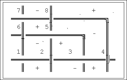 Indeed,
if we consider the polygons limited by the frames, we see that their sides
are always segments of frames between two crosses, or, if the frame bends,
the fragment between crosses will give more sides, as shown in the schema.
Let us consider as positive the polygon whose sides begin in an up position
and finish down when going in the clockwise direction of gyration , and
negative the opposite, as can be seen in the schema. Since only two frames
intersect at a time (R10), their crossing creates four angles, two
contiguous polygons sharing only one segment of frame, and four polygons
sharing a node. Now, it is easy to see that, if we select a positive
polygon, those contiguous to it will be negative, and the other one, opposed
by the angle, positive. That gives give us a rule to intersecting: we choose
one polygon as positive and all the others will take their respective sign;
the frames will be then accordingly interwoven.
Indeed,
if we consider the polygons limited by the frames, we see that their sides
are always segments of frames between two crosses, or, if the frame bends,
the fragment between crosses will give more sides, as shown in the schema.
Let us consider as positive the polygon whose sides begin in an up position
and finish down when going in the clockwise direction of gyration , and
negative the opposite, as can be seen in the schema. Since only two frames
intersect at a time (R10), their crossing creates four angles, two
contiguous polygons sharing only one segment of frame, and four polygons
sharing a node. Now, it is easy to see that, if we select a positive
polygon, those contiguous to it will be negative, and the other one, opposed
by the angle, positive. That gives give us a rule to intersecting: we choose
one polygon as positive and all the others will take their respective sign;
the frames will be then accordingly interwoven.
ARDALAN, N. & BAKHTIAR,L.The sense of Unity. Chicago Press. Chicago, London, 1973,1979. AUDSLEY, W & G. Designs and Patterns from Historic Ornament. Dover. N.York.1968. ABOU-ESH, I.M. Design Concepts of Islamic Arquitecture. Dar Al-Arabiyah. Beirut, 1970. BARKER, A.(ed):Greek Musical Writings,book II:Harmony&Acoustic Theory. Univ. Pres. Cambridge. 1989 BOURGOIN, J. Arabic Geometrical Pattern & Design. Dover, N.York. 1973. BOURGOIN, J. Islamic Patterns. Dover, N.York. 1977. BURCKHARDT, T. Moorish Culture in Spain. Allen & Unwi. Lond,1972. BURCKHARDT, T. Art of Islam. Language and Meaning. World of Islam Festival. London, 1976. CABANELAS, D. "El Techo del Salón de Comares en la Alhambra". Patronato Alhambra. Granada, 1988. COXETER, H.S.M. Regular Polytopes. Dover, N.York.1973. CRITCHLOW, K. Islamic Patterns. Thames & Hudson, London, 1992. GHICA, M.C. Estética de las Proporciones en la Naturaleza y en las Artes. Poseidón. Barcelona, 1977. GRABAR, O. Los fundamentos del arte islámico. Cátedra, Madrid, 1984. JAWAD al-JANAB, T. Studies in Medieval Architecture. Ministry of Culture & Information Baghdad, 1982. MARTÍNEZ, B. "Carpintería Mudéjar Toledana". Cuadernos Alhambra,12. 1976. NUERE, E. La Carpintería de Armar Española. Ministerio.Cultura. Madrid, 1989. NASR,S.H. Islamic Art and Speirituality. Golgonooza. Ipswich, 1987. PHIGEL,S. Anadolu Selçuklulari'nin Ta Tezyinati. Türk Tarih Korumu Basimevi, Ankara,1987. PAVÓN MALDONADO, B. El Arte Hispano-Mulsulmán en su Decoración Geométrica. Min. Cultura y Agenc. Española. Cooperación Internacional. Madrid, 1981, 1990. PRIETO y VIVES, A. El Arte de la Lacería. Coleg.Ingen. Caminos Canales Puertos. Madrid, 1977. RADEMACHER & TOEPLITZ. Números y Figuras. Alianza, Madrid,1970. SÁNCHEZ, A. Trigonometría Rectilínea y Esférica. Lib.Romo. Madrid, 1944. SÁNCHEZ, F.J. "ESCALA, Automatic Measurement of Oriental Scales". Proc. ICEMCO. Univ. Cambridge. London, 1993a. SÁNCHEZ, F.J. (1993-b.) "PUERTRA: a Model of Islamic Rectilinear Interlaced Lattices". Proc. 4th. ICEMCO. Cambridge: Univ. Cambridge. SÁNCHEZ, F.J. (1995) "A Model of Islamic Rectilinear Interlaced Lattices". Interactive Internet version: <http:www.anglia.ac.uk/~trochford/puertra4.html> SÁNCHEZ, F.J. (1996.) "Lacework Analysis: Three Tilework Panels from Isfahan". Proc. 5th ICEMCO, Cambridge. Cambridge: Univ. Cambridge. SPELTZ, A. The Styles of Ornament. Dover, N.York. 1959. VARDERBROECK, A. Philosophical geometry. Inner Traditions Inter. Rochester, 1972. WILSON, E. Islamic Designs. Dover. N.York. 1988.
$ Contents
# Contents
+ 00001
$ Getting Started
# Getting_Started
+ 00002
$ Rige
# Rige
+ 00003
$ Lattice
# Lattice
+ A:00001
$ Order
# Order
+ B:00001
$ Angles
# Angles
+ B:00002
$ Distances
# Distances
+ B:00003
$ Symmetries
# Symmetries
+ B:00004
$ Generative Element
# Generative_Element
+ A:00002
$ Translation Element
# Translation_Element
+ A:00003
$ Metabolai
# Metabolai
$ Formal Rules
# Formal_Rules
+ A:00005
$ Commands
# Commands
+ 00004
$ Plane Transformations
# Plane_Transformations
+ C:00001
$ Block Displacements
# Block_Displacements
+ C:00002
$ Spatial Transformations
# Spatial_Transformations
$ Spatial Surface
# Spatial_Surface
$ Frames
# Frames
$ References
# References
+ 00006
The first step to edit (change an already existing Rige is to change the Lattice on which the Rige is drawn: this is done by its Lattice Edition. The edition of a Rige itself consists in the modification of some of the Polygonal lines that compose it, and in the choice of the covering polygonal in each intersections, that is the Polygonal Drawing Order. The Edition utility directs you through all these polygonals and prompts you to accept, for all their segments, their Angles and Distances index ‒their values were given in Lattice Edition. You can change the proposed index by using the '+' and '-' keys, which vary accordingly their values; or you can type the desired values. It is also possible to 'kill' some segments or to 'introduce' new ones, as well as to 'part' some polygonals in two branches, copy them for independent edition,
You can also choose the order in which the polygonals are drawn; this implies which polygonals cover the others at their intersections: any one is then covered by all the following. This choice is not always easy, and sometimes you must cut one of the polygonals in two halves: think in three intersecting straight lines, as they appear in the figure included in the Frames topic (the two rectangles in the right side): one of them must be halved in order to comply with the "one above, one below" rule, the R12 in Formal Rules. This also happens in the opening Rige INI.RIG. Edit its eight polygonals and see how this frame halving achieves a correct covering.
This reordering has been made easy by Puertra ‒ with respect to previous versions‒, by numbering each polygonal on the screen, so allowing the user to alter the ordering in a friendly interactive basis.
So, in its maximum complication, a figure designed with Puertra can include several Rige; each Rige can include several Sublattices with their own parameters. On these Sublattices, several Polygonals are chosen, each one composed by several Segments.
$#+Lattice EditionLattice Edition is the definition of the Lattice on which the Rige is placed as on a frame, choosing some of its segments to draw the sheets or frames which compose this Rige. The Lattice is determined by the repetition by symmetries of the GE ( Generative Element) to form the TE (Translation_Element) and the repetition by translations of this TE to cover the plane (or some other surfaces). Therefore, the lattice edition is in fact the GE edition, which consists of the choice of the angles (Order), distances, size, etc..
The GE can include only one lattice, or several, in which case, the first of them is the one which defines the limits and symmetries of the GE, the others having their centers, situations and symmetry properties, inside the GE boundaries.
By typing '0' or clicking the 'Edition-Calcu' menu you access the standard Windows calculator, in which you can calculate appropriate values for your Distances.
All the required parameters, some particular of the GE some particular of the TE some of the lattice itself, are explained on the Input Box itself. Distances are changed gradually on the screen to adjust their mutual situations when the input values do not fit as expected, or to rest new combinations. Thus the lattice can be designed by exact values or on a trial and error basis.
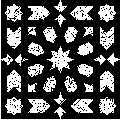
 Usually
the Translation Element
is displaced parallel to itself. But sometimes you must turn it with
each translation to achieve different figures. This is done for instance
in a beautiful 'leaves' design found in Alhambra of Granada
(Spain), where each translation is accompanied by a half turn ‒both for
black and white leaves. You can also change it during Lattice Edition.
Usually
the Translation Element
is displaced parallel to itself. But sometimes you must turn it with
each translation to achieve different figures. This is done for instance
in a beautiful 'leaves' design found in Alhambra of Granada
(Spain), where each translation is accompanied by a half turn ‒both for
black and white leaves. You can also change it during Lattice Edition.
 Usually
the Generative Element
is rotated spatially , that is, turned around an axe, as book
leaves, forming axial Symmetries.
But this turn can also be on a plane, becoming only a circular symmetry,
the figure thus taking a swastika aspect, as the one besides.
This effect is also achieved with key '!'.
Usually
the Generative Element
is rotated spatially , that is, turned around an axe, as book
leaves, forming axial Symmetries.
But this turn can also be on a plane, becoming only a circular symmetry,
the figure thus taking a swastika aspect, as the one besides.
This effect is also achieved with key '!'.
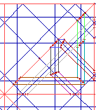
Any Rige is composed by several interlaced polygonals. A polygonal is composed by several straight segments connected at their extremes (if they compose a closed figure, it is called a polygon). These segments belong to the lattice straight lines.
 Each lattice line is defined and coded with two parameters: 1. Its Angle
with the reference or basic angle (usually 0º but sometimes another
one); and 2. Its Distance to the Center, an arbitrary point (usually the
figure center but often another point). Therefore a segment is
defined by means of 3 straight lines, the one to which the segment
belongs (the line) and those that intersect it in the segment
extremes (ends). The segment coding consists of these three
straight line codes in the order: end, line, end. as can be seen
in the first figure.
The polygonal is
then easily coded by listing its segment codes: and since any second
end is the line of the next segment, only the first end of
the first segment and the second end of
the last segment are needed besides the lines of each segment.
For instance, in the second figure, the lower horizontal segment, the
'green' one, is coded as follows: (1,0) (angle 1, in 8-lattice,
so 45º; and distance 0, crossing the center. (0,-1) (angle 0, 0º
, the reference angle; and distance -1, since it is the first after the
one passing on the center ( the negative sign means that when you go
away from the center along this line, the center is on your right; it
would be positive if it fell on your left). The following line, the
second end of the segment, is the green vertical: (2,3), since
its angle is the second in 8-lattice, 90º, and its distance the third,
positive because the center is on its left.
But you will see
that with this coding, the union of both frames would have an angle of
45º, instead of the 135º, to link correctly with the vertical line. The
reason is that you change from negative distance to positive: in that
case you need to insert an extra code that 'bends' the frame: the code
is the pair (-1,-1) meaningless as line code. Thus the complete
sequence is: ( 1,0) ; (0,-1) ; (-1,-1) ; (2,3).
(parentheses, commas and semicolons are used here for clarifications,
they are not actual codes).
There is an
additional extra code, the pair (-3, -3); it happens only when
there are more than one lattice in the figure and you change from one to
another, so that angle and distance codes mean different lines. The code
change the lattice to the next, coming back to the first when you reach
the last one). You can also use the index of the desired lattice, i.e.,
'k', as the second number of the pair, which becomes then (-3, k).
However, in
Lattice Edition
you are helped by Puertra to make your choice since the selected line
blinks, so you can see if it is the desired one, and change it if not.
Finally, remember
that, in Puertra, every counting begins at 0, not 1 ‒the first distance
is the distance 0, the second the distance 1, and so on. An exception is
the polygonal order of drawing, which begins in 1. Sorry!
Each lattice line is defined and coded with two parameters: 1. Its Angle
with the reference or basic angle (usually 0º but sometimes another
one); and 2. Its Distance to the Center, an arbitrary point (usually the
figure center but often another point). Therefore a segment is
defined by means of 3 straight lines, the one to which the segment
belongs (the line) and those that intersect it in the segment
extremes (ends). The segment coding consists of these three
straight line codes in the order: end, line, end. as can be seen
in the first figure.
The polygonal is
then easily coded by listing its segment codes: and since any second
end is the line of the next segment, only the first end of
the first segment and the second end of
the last segment are needed besides the lines of each segment.
For instance, in the second figure, the lower horizontal segment, the
'green' one, is coded as follows: (1,0) (angle 1, in 8-lattice,
so 45º; and distance 0, crossing the center. (0,-1) (angle 0, 0º
, the reference angle; and distance -1, since it is the first after the
one passing on the center ( the negative sign means that when you go
away from the center along this line, the center is on your right; it
would be positive if it fell on your left). The following line, the
second end of the segment, is the green vertical: (2,3), since
its angle is the second in 8-lattice, 90º, and its distance the third,
positive because the center is on its left.
But you will see
that with this coding, the union of both frames would have an angle of
45º, instead of the 135º, to link correctly with the vertical line. The
reason is that you change from negative distance to positive: in that
case you need to insert an extra code that 'bends' the frame: the code
is the pair (-1,-1) meaningless as line code. Thus the complete
sequence is: ( 1,0) ; (0,-1) ; (-1,-1) ; (2,3).
(parentheses, commas and semicolons are used here for clarifications,
they are not actual codes).
There is an
additional extra code, the pair (-3, -3); it happens only when
there are more than one lattice in the figure and you change from one to
another, so that angle and distance codes mean different lines. The code
change the lattice to the next, coming back to the first when you reach
the last one). You can also use the index of the desired lattice, i.e.,
'k', as the second number of the pair, which becomes then (-3, k).
However, in
Lattice Edition
you are helped by Puertra to make your choice since the selected line
blinks, so you can see if it is the desired one, and change it if not.
Finally, remember
that, in Puertra, every counting begins at 0, not 1 ‒the first distance
is the distance 0, the second the distance 1, and so on. An exception is
the polygonal order of drawing, which begins in 1. Sorry!Any Rige can be stored in and retrieved from a disk as files with the extension RIG, such the initial one, called INI.RIG, loaded at start time from the directory where Wpu21.EXE is placed ‒otherwise a warning is issued, and the user must find and open by himself another RIG file to run the program. The file INI.RIG is provided within the PUERTRA package, but the user can choose another and call it INI.RIG.
At any time during the running of Wpu21, the user can store the actual Rige, with all its parameters, into a new file with a chosen name. He can make subdirectories to classify his/her RIG files according to their properties (i.e., according their Order or their Color).
The RIG file is written in ASCII code and can be seen in any ASCII editor (such as NOTEPAD in Windows) and even modified there; however only experienced users should do that, the proper way being to modify sizes, colors, parameters with the user Commands , Lattice Edition and Rige Edition.
For stored Riges, the user must be aware of the printing properties of numbers in the the Operating System: specially the decimal separator in fractional numbers must be a full stop or point ( . ), rather than a comma ( , ), otherwise an error would occur. Thus 2.23 is acceptable, but 2,23 is not.
The Graphics patterns generated by Puertra can be grabbed by the 'PrintScreen' Windows utility, pasted in any Graphic Editor (such as PAINTBRUSH or PSP) and be modified there. Graphic files (such those in BMP, TIFF, GIF or JPG formats) can then be stored, printed or included in the user's documents (as this Help file shows).
Now you know the concepts used by Puertra in Rige study. But, how to interpret them in the analysis of an actual Rige found in a Mosque wall, for instance?. The analysis will follow the following steps, divided in sections: LATTICE, Rige, COMPLEMENTS. I. LATTICE 1. Order of the Lattice on which the Rige is chosen. Count how many different Angles are present in the analyzed form, and find the minimal circle division that produce these angles with respect a reference angle (0º or otherwise). The found divider is the Order we were looking for. 2. Find the Distances between the family of parallels to each one these angles. Check if all this distances can be expressed as linear combinations of only 1 (rare), 2 (probable, look for it), or more (probably unnecessary). Establish the series of these distances for each one of the angles, and check if the series are equal, or equal to 2 types (alternate), or more. These are the Subseries you are asked for during Lattice Edition. 3. Find the Center of your figure. Probably it is the obvious center of a highly symmetrical form; but sometimes you must choose it among several indifferent possibilities. The center is important because it is the Rotation Center of several Symmetries that usually appear in the Rige subject. 4. Find the GE (Generative Element ) of your form. This is the minimal part ( or one of the minimal parts) that generates the symmetrical form or one of its parts. The rotation of this GE around the center, either axially (see Symmetries ) or by means of Circular Repetitions generates the mentioned symmetrical form, which must now copied be translation, thus becoming the TE: 5. Translation Element (TE) It can be simply translated to cover the plane, or, sometimes be submitted to a Gyrated Translation . The horizontal and vertical distances between contiguous TE's must be ascertained, as well as the occurrence of a displacement between rows of TE. 6, Once you have defined the GE and the TE, you have the Lattice (with one or several Sublattices). II. Rige 7. On the canvass or net that crosses the GE, you must choose several Polygonals which, intersecting and interlacing reproduce the actual case being analyzed. You can use long Polygonals composed by many segments (up to 25) or very short ones, composed by only 1 segment ‒codified however by 3 segment codes: End, Line, End, as it is explained in the Polygonals topic. 8. Now you must determine the Draw Order (please do not confuse this order with the Lattice Order seen in Step 1 !) in which you place your polygonals. This is easy with short ones, but even then you must have a clear numbering of this Draw Order to avoid repeating the process in Rige Edition. If you define your Polygonal in the correct draw order, it is not necessary specify another one when prompted for it after the Polygonal coding. 9. You can type 'r' on the Puertra display to see the TE develop until the entire plane is covered. III. COMPLEMENTS. 10. Once you have defined the essential characteristics of the Rige, some complements must be chosen to complete the global visual effect. They are described in Rige Finishing, Background, Colors, Boundaries, Manual Draw, Lines, and Boundaries. The Rige and its Lattice are already defined. But there are still several operations to be done before it takes the desired aspect. You can change all the Colors that compose the Frames, and the Background. You can also limit the figure by predefined Boundaries, necessary to shape properly the Rige. You can also make some small touches by Manual Draw.
 It is
made with a solid color covered by small lines ‒like a texture-. You
can change the Colors of
both. But you may use another Rige as a textured background: take
one, even the same and make the scale much smaller than the main Rige.
If the scales of both are in a simple relationship (4, 8, 16) the same
figures of the background Rige will appear in the same elements of the
foreground Rige. Occasionally you can use another ‒even the same‒ Rige
as a texture background, that is, a small size figure that contrasts, in
color, form, order with the upper form, as the figure shows. Results are
more harmonious when simple ratio sizes are used; but non-related sizes
could fill the texture function better. Try.
It is
made with a solid color covered by small lines ‒like a texture-. You
can change the Colors of
both. But you may use another Rige as a textured background: take
one, even the same and make the scale much smaller than the main Rige.
If the scales of both are in a simple relationship (4, 8, 16) the same
figures of the background Rige will appear in the same elements of the
foreground Rige. Occasionally you can use another ‒even the same‒ Rige
as a texture background, that is, a small size figure that contrasts, in
color, form, order with the upper form, as the figure shows. Results are
more harmonious when simple ratio sizes are used; but non-related sizes
could fill the texture function better. Try.
Color is a art in itself. A judicious use of it is necessary to avoid a too colorful and childish combination. The problem is how to reduce the enormous computer possibilities to reach an harmonious combination. Let see some suggestions: 1. Use as few colors as possible. Two are the minimum, to have figures against a background. 2. Contrast frames against the rest. 3. Contrast not only colors themselves (hue) but also their luminosity. This is achieved when the figure stands even when converted to black and white.
 According to this philosophy, only six simultaneous colors are used in
our Puertra program. They are called Item Colors, and their names are:
1. Lines, 2. Background or Filling, 3. Lace (frame background), 4. Lace
Line, 5.Veladura (Dry brush effect), and 6. GE (Generative
Element Boundaries). See their effect in the figure. You can see these
colors with commands 'u', change the actual Item Color with 'C, and
change its main hue with command 'c'. See these and others commands in
Color.
According to this philosophy, only six simultaneous colors are used in
our Puertra program. They are called Item Colors, and their names are:
1. Lines, 2. Background or Filling, 3. Lace (frame background), 4. Lace
Line, 5.Veladura (Dry brush effect), and 6. GE (Generative
Element Boundaries). See their effect in the figure. You can see these
colors with commands 'u', change the actual Item Color with 'C, and
change its main hue with command 'c'. See these and others commands in
Color.
The Rige and its Lattice, theoretically infinite, are limited either by the display limits or by special boundaries adopting different shapes and borders. These are: Square, Rhombus, Door, Circle, Polygon, Star, Arch. The sizes of some of these shapes conform with the Lattice and Rige characteristics, to harmonize them with the form inside; but these sizes can also be changed, by means of a factor. The shapes can be done by a clean cut of the figure, or be adorned with a border made with the actual frame used in the Rige itself. Type 'p' or use the Menu.
 Perhaps
you might want to add some lines or symbols to the figure, to see the
effect of a new straight line or make an illustrative sketch. Use then
the mouse, Click Left button for points (small circles), Left moving for
continuous curved lines, Right moving for straight lines ‒they will be
circles instead, if you DoubleClick Left first (please not Right because
you would change color); do it again and they will be straight lines
once more. Click Right to pick up the pixels Colors
to be used in the following drawings ‒you have the Lattice Line color
as beginning default. You can also change the Width of each one of these
lines, to mark some of them as important. Note that picking up the
background color (white or otherwise) you can actually erase previous
lines.
While moving, you
will see in the window's caption (where the titles are) the actual
values of the point coordinates (for Left button) or both the initial
and the present point coordinates, together with the line inclination
(angle with the horizontal) and the distance between both points (for
the Right button).
Press a k
Perhaps
you might want to add some lines or symbols to the figure, to see the
effect of a new straight line or make an illustrative sketch. Use then
the mouse, Click Left button for points (small circles), Left moving for
continuous curved lines, Right moving for straight lines ‒they will be
circles instead, if you DoubleClick Left first (please not Right because
you would change color); do it again and they will be straight lines
once more. Click Right to pick up the pixels Colors
to be used in the following drawings ‒you have the Lattice Line color
as beginning default. You can also change the Width of each one of these
lines, to mark some of them as important. Note that picking up the
background color (white or otherwise) you can actually erase previous
lines.
While moving, you
will see in the window's caption (where the titles are) the actual
values of the point coordinates (for Left button) or both the initial
and the present point coordinates, together with the line inclination
(angle with the horizontal) and the distance between both points (for
the Right button).
Press a k ey while
the mouse Left button is also pressed, to write the key alphanumeric
symbol besides the point or line. Useful symbols, numbers and words can
be added in this way in particular points of the figure. The font size
can be changed in the window menu (Manual/Font).
These simple tools allow you to make useful diagrams over your Rige
or Lattice. With the
Frame/Line menu item, you switch between simple lines and frames,
similar to the ones used in your actual Rige. In this way it is possible
to try the visual effect of new lines, before introducing them as part
of some polygonal.
Also, when the
Fill menu item is set (Yes), any shape can filled with the Filling color
defined in Colors: simply click
within the shape.
ey while
the mouse Left button is also pressed, to write the key alphanumeric
symbol besides the point or line. Useful symbols, numbers and words can
be added in this way in particular points of the figure. The font size
can be changed in the window menu (Manual/Font).
These simple tools allow you to make useful diagrams over your Rige
or Lattice. With the
Frame/Line menu item, you switch between simple lines and frames,
similar to the ones used in your actual Rige. In this way it is possible
to try the visual effect of new lines, before introducing them as part
of some polygonal.
Also, when the
Fill menu item is set (Yes), any shape can filled with the Filling color
defined in Colors: simply click
within the shape.
MOUSE USE IN PUERTRA Action LEFT RIGHT Click Circlet PickUp Color Move Curve Shape Key Prints character Two Clicks Fill with Filling ColorDblClick Switch Shape: (Straight, Circle, Rectangle, Star, Polygon, Arch...)These manual modifications only affect the present figure, and are not saved with the Rige parameters. Therefore, grab and print the figure before changing it. During all the drawing process (manual or automatic) you can change some characteristics of the drawn lines: their Width, with four values ‒default is Min(imal); the Mode, a rotating switch of 16 possibilities, to find effects of fantasy while moving the figure around; the Erase possibility (one of the former 16 modes) of seeing the figure transformations with or without erasing the previous situations ‒default is Yes.
$#+Untitled 1
Contents
Getting Started
Rige
Lattice
Order
Angles
Distances
Symmetries
Generative Element
Translation Element
Metabolai
Formal Rules
Commands
Plane Transformations
Block Displacements
Spatial Transformations
Spatial Surface
Frames
References
Rige Edition
Lattice Edition
Gyrated Translation
Circular Repetitions
Polygonals
Files
Rige Analysis
Rige Finishing
Background
Colors
Manual Draw
Lines
Boundaries
$ Rige Edition
# Rige_Edition
+ 00001
$ Lattice Edition
# Lattice_Edition
$ Gyrated Translation
# Gyrated_Translation
+ B:00001
$ Circular Repetitions
# Circular_Repetitions
$ Polygonals
# Polygonals
$ Files
# Files
+ A:00003
$ Rige Analysis
# Rige_Analysis
+ A:00004
$ Rige Finishing
# Rige_Finishing
+ 00002
$ Background
# Background
$ Colors
# Colors
+ C:00002
$ Boundaries
# Boundaries
$ Manual Draw
# Manual_Draw
+ C:00004
$ Lines
# Lines
+ C:00005
$ Untitled 1
# Untitled_1
Vuelta al Principio Última
actualización:
sábado, 04 de febrero de 2017 Visitantes: